Primary Parameters
The primary parameters are listed below, these are the building blocks for manipulating the waveshape. Each of the primary parameters can be modulated in various ways with respect to the output of other internal channels, as well as CV inputs.
Waveform
Adjust the waveform of the given channel. The available waveforms are listed in the table below:
| Waveform | Description | Morph To/Fn. | Image |
|---|---|---|---|
Sin | Sine | Exponential | 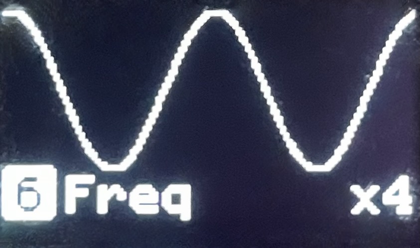 |
Tan | Tangent | Linear | 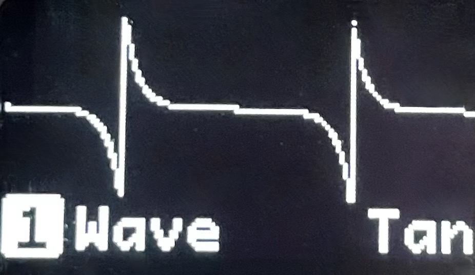 |
Tri | Triangle | Sawtooth | 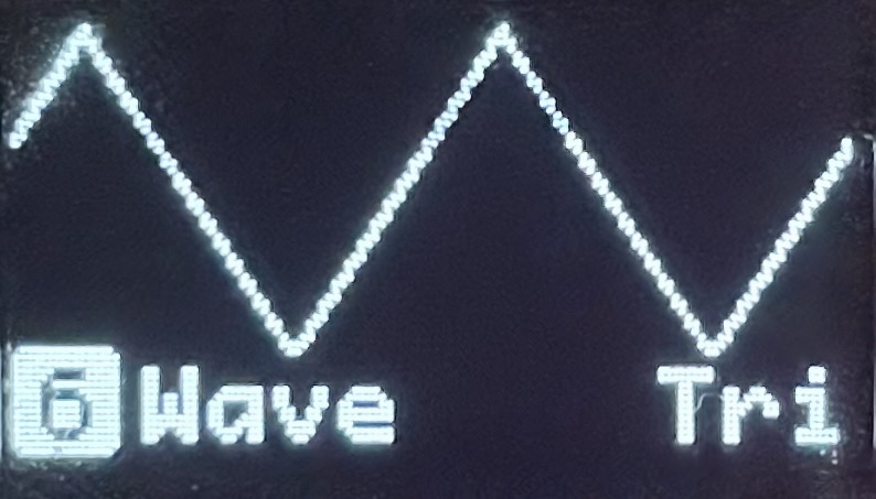 |
Squ | Square | Duty cycle | 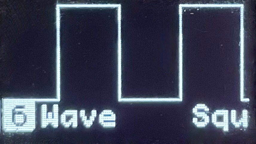 |
Rand | Random | Slew, Blend | 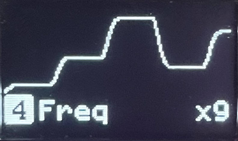 |
Lorenz | Lorenz Chaos | Mix X-Y-Z |  |
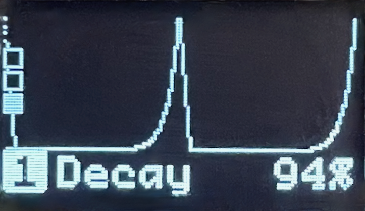
Env | Envelope | Attack, Skew, Decay | 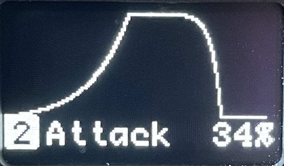 |
Step | Stair Step | Number of Steps | 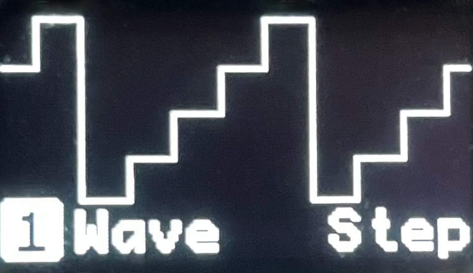 |
In | Inputs | Mix CV inputs | 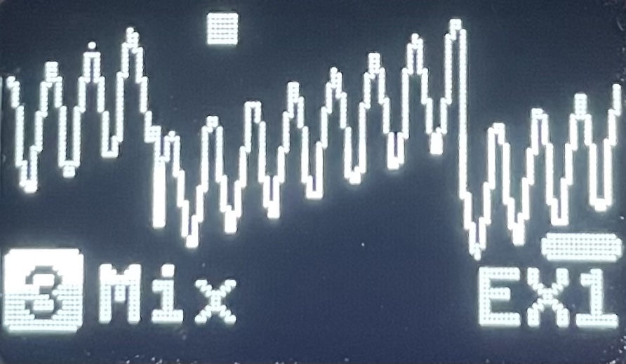 |
Out | Outputs | Mix other outputs | 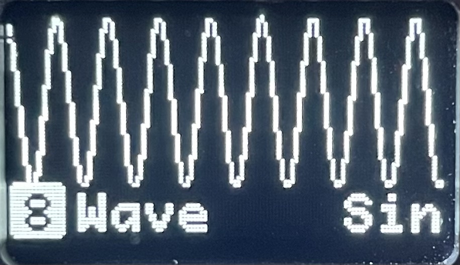 + + 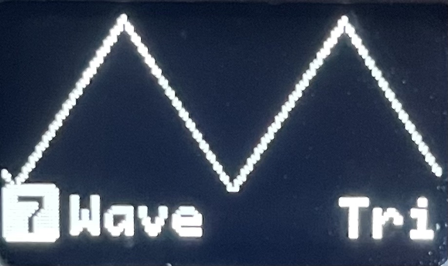 = = 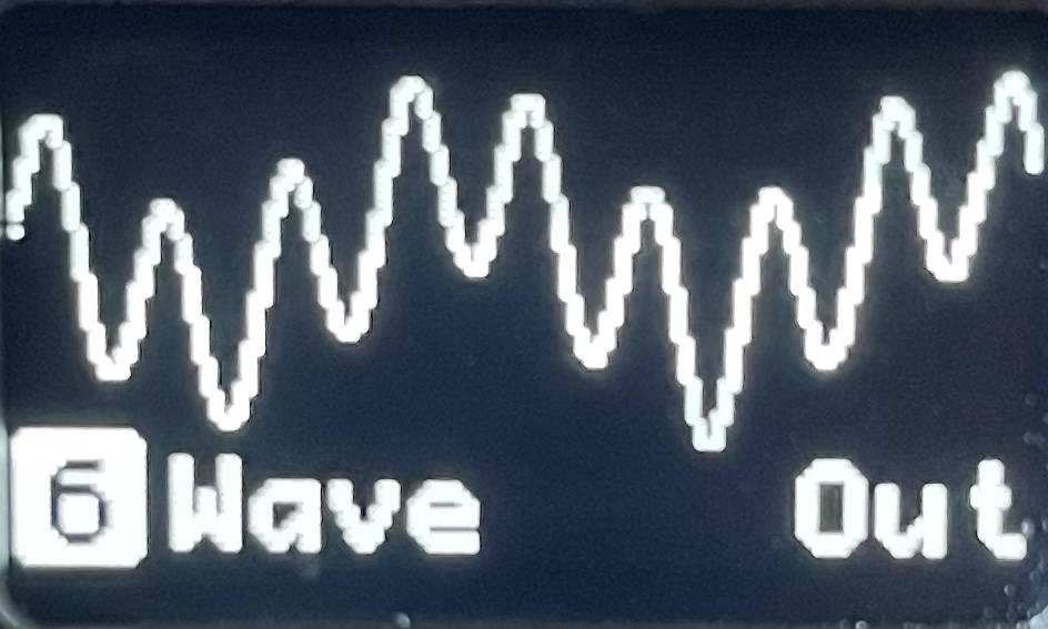 |
Frequency
Adjusts the Frequency of the given channel. Frequency can either be Synchronized (relative to the BPM) or Desynchronized. When synchronized the maximum and minimum frequencies are BPM * 128 and BPM / 128 respectively and when desynchronized they are 128Hz and 1mHz. When operating in Trigger Mode and Desynchronized the unit changes to seconds.
The frequency is disabled in certain circumstances:
- When the
InputorOutputwaveform is selected
💡 LONG HOLD FREQ - to switch between Synchronized or Desychronized modes |
Settings
- Curve Modulation Settings
SynchronizeorDesynchronized
Amplitude
Adjusts the Amplitude of a given channel. When in Bipolar or Polar modes the amplitude range is 10Vpp (-5.0V to +5.0V) or 5Vpp (0.0V to +5.0V) respectively. The amplitude can go into negative which inverts the signal. This feature also is applied to the modulation, but can be configured.
Settings
- Curve Modulation Settings
- Inversion Modulation
POS: Positive modulation only - modulation output will range from 0% to 100%. No inversion is applied.INV: Inversion modulation - allows the modulation output to range from -100% to 100%, in which inversion can be applied.
Bipolar/Unipolarmode
Offset
Adjusts the Offset of a given channel. At a value of 0 there is no offset being applied, e.g. the waveform is generated within the middle of the amplitude range. At a value of +50 the waveform is generated at the top of the amplitude range, and a value of -50 the waveform is generated at the bottom of the amplitude range.
Settings
Morph
The Morph parameter varies depending on the waveform and adjusts the shape of the waveform accordingly. See the above waveform table for details about how the morph effects each waveform shape.
💡 LONG HOLD MOR - to switch between morph components (currently only for Random and Envelope waveforms) |
Settings
- Curve Modulation Settings
- Mod selector (only available for
Mix)
In & Out: Mix
The Mix parameter is available when using the In or Out waveforms and is accessible via the Morph parameter button. Mix allows mixing between the different waveforms available - mixing between adjacent sources. The horizontal bar indicates the amount of mixing between the currently selected source, and the neighboring source.
For example when using the In waveform, and you have CV2 selected, when the horizontal bar is toward the left, then you are mixing toward CV1, when the horizontal bar is toward the right then you are mixing toward CV3, when no horizontal bar is present then no mixing is taking place.
Envelope: Attack, Skew and Decay
The Attack, Skew and Decay parameters are available when using the Env waveform and are accessible by using via the Morph parameter button. These parameters control the envelope characteristics.
 Multi-component parameter (Envelope)
 Random: Slew and Blend
The Slew and Blend parameters are available when using the Random waveform. Slew changes the duration between randomly generated values, while Blend mixes between the last random value and an entirely new random value.
Phase
The Phase parameter allows periodic waveforms to be phase locked to varying degrees, or not locked at all. When the phase is locked any adjustment to frequency will cause the phase to be recalculated (this can cause visual discontinuities in the waveform which is normal).
The phase is disabled in certain circumstances:
- When
Frequencymodulation is active - When the
InputorOutputwaveform is selected
Settings
- Curve Modulation Settings
- Trigger Source: Will reset the Phase of a channel. In
Continuous modethis will only have an effect whenPhaseis set toFree ContinuousorOne-shotmode: When inContinuousthe waveform repeats, e.g. an LFO. InOne-shot, it plays once and stops, e.g. Function generator.